| System | Cutoff Frequency ( fc, Hz) |
Settling Time (ts, s) |
Gain (G) |
|---|---|---|---|
| Mechanical | D2πM | 4ω0=4MD | 1M |
| Electrical | 12πRC | 4ω0=4RC | 1RC |


In the time domain first order systems are the solution y(t) of the following differential equation {dy(t)dt=−ω0y(t)+Gu(t)y(0)=y0 where all the quantities are scalars, y0 is the initial condition of y(t), u(t) is the input of the system and G and ω0 are constants.
In the Laplace domain (1) becomes Y(s)=H(s)U(s)+H(s)Gy0,withH(s)=Gs+ω0 where H(s) is the transfer function of y(t).
From now on we will consider y0=0 and under this condition (2) becomes Y(s)=H(s)U(s)
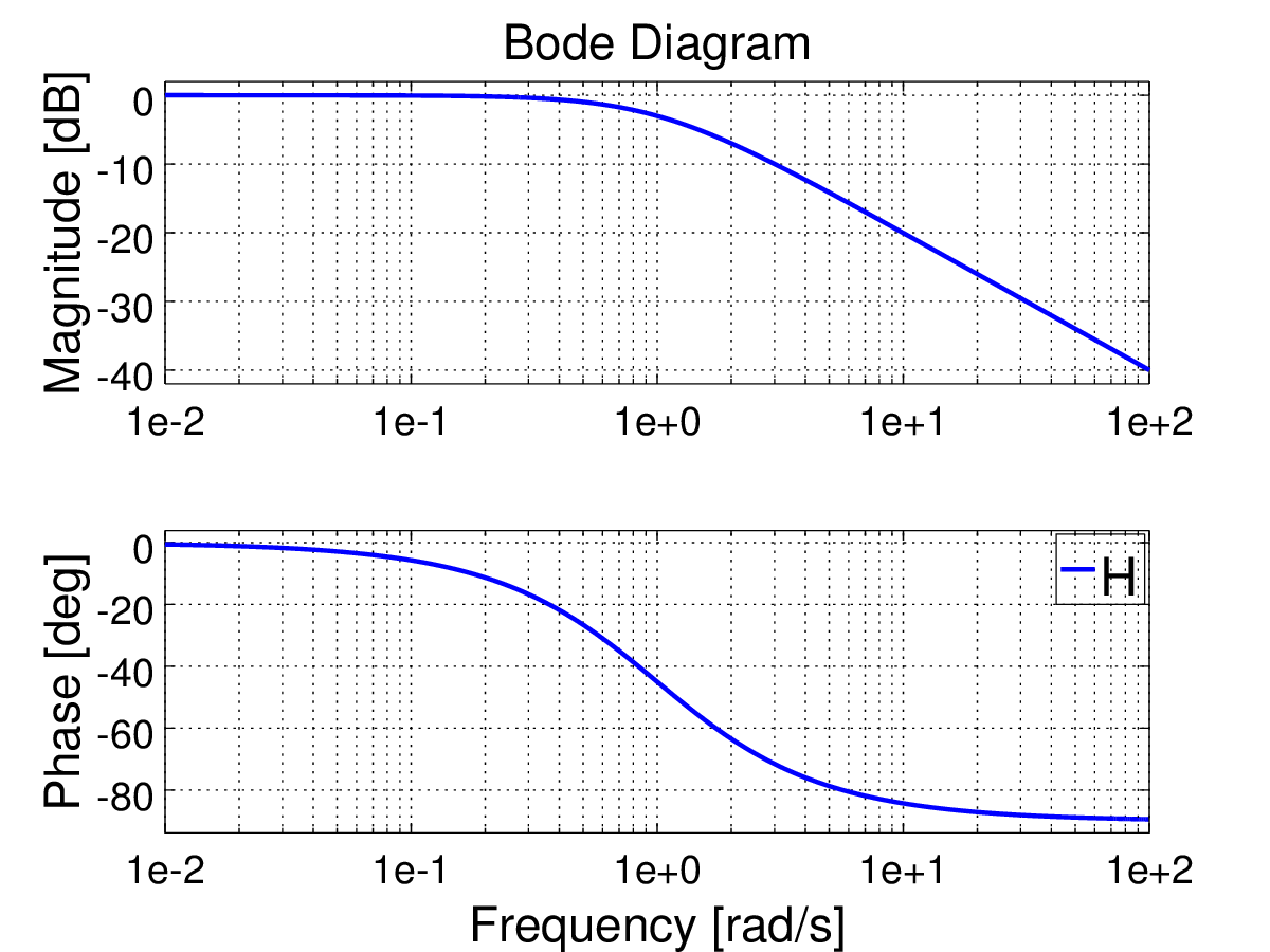
If ω0>0, which is usually the case for physical systems of this type, (1) is asymptotically/BIBO stable (asymptotic and BIBO stability are equivalent for first order systems) and the time response to the step function u(t)={1if t≥00if t<0 is shown in figure 1 while figure 2 represents the Bode plot of H(s).


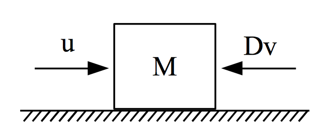
In the mechanical domain a first order system can be built using a mass force system with viscous damping, (M, u and D respectively, see figure 3). From Newton we have Ma=u−Dv which can be represented through velocity as Mdvdt=−Dv+u⟹dvdt=−DMv+1Mu Comparing (4) with (1) we have that for a mechanical system y=v, G=1M and ω0=DM. A small note is made on ω0 which is positive implying that the system is stable.
In the Laplace domain (4) becomes sMV=−DV+U⟹V=UsM+D⟹V=1M1s+DMU
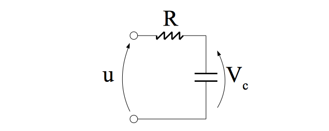
In the electrical domain a first order system is represented by an RC circuit (figure 4) . Using Kirchhoff's voltage law we have u=iR+vci=Cdvcdt⇒RCdvcdt=u−vc⟹dvcdt=−1RCvc+1RCu From Laplace we obtain sVc=−1RCVc+1RCU⟹Vc=1RC1s+1RCU and comparing (6) with (1) (or equivalently (7) with (3)) it can be seen that y=vc, G=1RC and ω0=1RC. A small note is made on ω0 which is positive implying that the system is stable.
Also known as corner or break frequency, the cutoff frequency decreases the energy flow through a system and obstructs it from working as intended.
The cutoff frequency of a first order system can be found by analysing the magnitude of H(jω) (Figure 2) |H(jω)|=G√ω2+ω20 |H(jω)| behaviour can be assessed considering that it is monotonically decreasing and it has two asymptotes, that is |H(jω)|≃{H0=Gω0if ω≪ω0HR=Gωif ω≫ω0 These properties guaranty that there is a cutoff frequency and it can be calculated by finding where H0 and HR intersects (from (9), H0 is constant while HR is a function of ω), that is H0=HR(ωc)⟹Gω0=Gωc and the cutoff frequency is {ωc=ω0[rad/s]fc=ω02π[Hz] From here we can also find that |H(jωc)|=1√2Gω0⟹|H(jωc)|=1√2H0 which shows that in ω=ωc, |H(jω)| loses 3dB (=20log(√2)).
Figure 2 shows an example where ω0=1.
For the two systems described in the above examples the cutoff frequency (Hz) is Mechanical:fc=D2πMElectrical: fc=12πRC
The settling time of (1) can be calculated in the Laplace domain applying the step function u(t)={1if t≥00if t<0L ⇒1s to (3). The response becomes Y=Gs(s+ω0) which can be written as Y=Gω0(1s−1s+ω0) and returning back to the time domain we obtain (t≥)0 y(t)=Gω0(1−e−ω0t) Now, to find the rise time we will need the settling value of (13) and to do this we take its limit as limt→∞Gω0(1−e−ω0t)=Gω0 Defining (ts) as the time required to reach 98% of (13)'s final value then from (13) and (14) we obtain the following equation 0.98Gω0=Gω0(1−e−ω0ts)⟹0.98=1−e−ω0ts⟹ts=−ln(0.02)ω0 and from here we finally calculate the settling time as ts≃4ω0 For the two systems described in the above examples the settling time is Mechanical:ts=4MDElectrical: ts=4RC